Hind Wheels (April 2020)
The rims were the first stage of the next phase where I started by turning the nearly 50-year old aluminium castings to size. I have a Colchester Bantam 2000 lathe, which easily contained the 9” over the bed; however, a wooden jig was required to mate between the face plate and casting to fixture the job for profiling all round. I found the interesting part of this job was contending with the resonance of what is a very thin, walled, large-diameter tube. I found that a ‘very sharp’ HSS tool with a 1mm rad at the cutting tip was the way to go with the lathe running as slow at it would go.
The rims were the first stage of the next phase where I started by turning the nearly 50-year old aluminium castings to size. I have a Colchester Bantam 2000 lathe, which easily contained the 9” over the bed; however, a wooden jig was required to mate between the face plate and casting to fixture the job for profiling all round. I found the interesting part of this job was contending with the resonance of what is a very thin, walled, large-diameter tube. I found that a ‘very sharp’ HSS tool with a 1mm rad at the cutting tip was the way to go with the lathe running as slow at it would go.
Marking out the spoke rivet holes around the T frames was a particular challenge, as I found it difficult to accurately divide the inner circumference by the 8 sectors, due to personal skill, having sufficiently sharp points on my dividers and being able to set the divides accurately enough. Needless to say, I had a few attempts working my way round to only discover the last leg did not align with the starting point.
With the rims marked, a jig was manufactured to locate the holes about the marks and that jig was made so that it could be used both on the inside and outside rims. These have a different rivet pattern with the outer starting outwards and the inner starting inwards. The jig was modelled in Fusion360 and cut out of the plate on the CNC mill. The holes were centred and drilled first and small tabs were left of the part, so that the jig could be cut from the stock and lightly finished by hand. Once made, it was a sequence of orientate the jig, clamp and drill until all four rims were complete.
Strakes & Spokes
The 72 stakes and 32 spokes were all pressings from Reeves and all needed hand finishing all-round to achieve the correct dimensional tolerance and surface finishes. Each spoke took around 22 minutes to complete, which gave plenty of bench time for contemplating the less repetitive and more interesting machining challenges ahead!
The spoke palms need an initial locating hole drilled in them for attachment to the rim which was easiest to do accurately with a fixture. The outline of the spoke was modelled in Fusion360 and, using an adaptive clearing milling cycle followed by a 2D contour, the fixture pocket was milled into a piece of scape aluminium. Each spoke was then loaded into the fixture and centred drilled, then the sequence repeated with the required 3/32” drill.
Each of the strakes came with the four holes stamped in them and, well, this was a source of much grief. The stakes are located by their holes, which were essentially all wrong, and the two rims angularly aligned by the strakes. What I found was that there were three ‘groups’ of strakes which all contained similar errors. I’m guessing that my total pile of stakes was from three different pressing set ups and none were aligned correctly. The holes I had made in the rims were spot on to the drawing; thus, when mated together the assembly was wrong.
To resolve this, I selected a group of stakes to fit in the wrong initial position and then made this error up as I did assembly in the wheel. What really hurt my OCD was that the groups of stakes with similar errors did not necessarily make up a full revolution of the rim. Therefore, the spacing between stakes does vary slightly, and unless you really interrogate them with a calliper, the untrained eye would never know. At this point my father did step in, having recently been to London museum which had a traction engine on display, and he got some pictures of the strake positions on that engine. It turned out I was chasing an accuracy which was very overlooked 100 years ago!
Finally, each of the stakes was twisted along their length to suit the helix that is formed when mated with the rim and then each clamped in position, riveted on the initial locating hole. Then, the sequence of drilling, countersinking, riveting followed, until all were fitted.
Finally, each of the stakes was twisted along their length to suit the helix that is formed when mated with the rim and then each clamped in position, riveted on the initial locating hole. Then, the sequence of drilling, countersinking, riveting followed, until all were fitted.
Wheel Assembly
Another MDF fixture was made to support the assembled rim and centre portion of the matching hub. As the hub spacing differed on each wheel, as did the width of the centre portion, the fixture required a mandrel at its centre that could be spaced off with two different washers, thus achieving the required offsets. The fixture was turned from two layers of 18mm MDF glued together and a mandrel made from an offcut of mile steel fix in position with a press fit, glue and wood screws.
Another MDF fixture was made to support the assembled rim and centre portion of the matching hub. As the hub spacing differed on each wheel, as did the width of the centre portion, the fixture required a mandrel at its centre that could be spaced off with two different washers, thus achieving the required offsets. The fixture was turned from two layers of 18mm MDF glued together and a mandrel made from an offcut of mile steel fix in position with a press fit, glue and wood screws.
Once the rim and hub were located on the fixture, each spoke could be fitted to its location. Both ends needed marking and bending to suit the offset and twisting along its length to suit its location on diamond shape hub. Particular attention needed to be made to ensure the spoke offset were just right; otherwise, when secured any error would pull the wheel out of true. The spokes were initially retained by 7BA bolts at the rim, which enable the rim to be flipped over to the other 8 spokes. The inner ends of the spoke were then drilled, tapped, countersunk and fitted with 8BA screws into the hub; the location of which was not too fussy as long as the screws did not break through into the groove in the centre of the hub.
At a number of points during the spoke-bending process the wheel was loaded on the hind axle in the lathe to check for run out and where some existed the assembly gently pulled true before recommencing assembly.
At a number of points during the spoke-bending process the wheel was loaded on the hind axle in the lathe to check for run out and where some existed the assembly gently pulled true before recommencing assembly.
Once all parts were made, the inner ends of the spoke were glued into position using Loctite 648, which provides a high temperate resistant and high strength bond, and the 8BA screws were fitted. Riveting could then commence.
Riveting The Spokes
An offset rivet set was required to reach the inner rivet snap between the T-frames and avoid the spokes. This was made from a ¾”thick piece of mild steel with a hardened and tempered snap fitted to the working end. I had initially planned on using iron rivets for the wheel; however, in practice I found that I could not achieve a reliable and repeatable method for hammering them to shape when cold, and following much practice, I even cracked a hardened snap due to the hammer force required to overcome the work hardening as the head was formed. Thus, I opted to use copper rivets instead. This was not ideal; however, for a model of this scale, copper rivets should be more than strong enough.
The riveting then took place in sequence of removing the BA fastener, inserting the rivet loading the wheel on the snap and hammering to shape. The rest of the the holes per spoke were then drilled using the rim as a guide and riveted as before.
With the stakes and spoke, there were 196 rivets in each wheel!
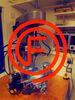
And finally after many hours of riveting and assembly the hind wheels were completed:
