
Water Gauge (March - November 2015)
The water gauge for the Allchin is another complicated affair involving three taper valves, numerous threaded joints and artistic profiles, most of which are not dimensioned on the drawings which leaves a great deal to the imagination of the builder! Here is an extract from the original drawing and that is about all the builder gets!
The water gauge for the Allchin is another complicated affair involving three taper valves, numerous threaded joints and artistic profiles, most of which are not dimensioned on the drawings which leaves a great deal to the imagination of the builder! Here is an extract from the original drawing and that is about all the builder gets!
The first task for this project was to produce a 3D model of the various parts using a 3D CAD program. All the available dimensions from the drawings were used and then rest were estimated until the model looked as similar as possible to prescribed drawing. One change that was made was the diameter of the glass tube as the specified 3/16" tube is now no longer commercially available, thus this was replaced with a 5mm tube and the interfacing parts modified to suit.
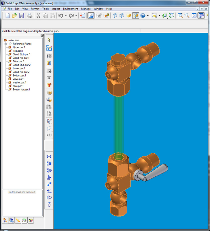
One notable omission from the drawings is any detail on the valve spindle, i.e. what angle the taper should be, its length, the diameter of the handle etc. This was frustrating as it was desired to keep the finished model as close to the drawings as possible. To overcome this challenge, the design was developed using details taken from similar items on the engine, notably the water pump bypass valve on SHT 11 and the injector water valve on SHT 1 are both very similar in size to the water gauge valves. The drawing for the cylinder drain cocks on SHT 14 also provides some written detail on the 6 deg inclusive taper angle and how to 'grind' the valves in. The finished 3D model is as follows:
One notable omission from the drawings is any detail on the valve spindle, i.e. what angle the taper should be, its length, the diameter of the handle etc. This was frustrating as it was desired to keep the finished model as close to the drawings as possible. To overcome this challenge, the design was developed using details taken from similar items on the engine, notably the water pump bypass valve on SHT 11 and the injector water valve on SHT 1 are both very similar in size to the water gauge valves. The drawing for the cylinder drain cocks on SHT 14 also provides some written detail on the 6 deg inclusive taper angle and how to 'grind' the valves in. The finished 3D model is as follows:
During production of the various parts it was found that classic 2D working drawings were not necessary as all the working information could be taken straight from the 3D model on the fly, although it helps having a PC monitor mounted about the lathe! In reflection with water gauge assembly turned out to be a very time consuming and fiddly assembly to make, as not only do all the parts have to interface with each other, the valves have to be very accurate to seal!
Firstly the hexagonal elements were made, i.e. the two glass retaining bezels, the top plug and drain pipe retainer. All these parts were machined from LG2 leaded bronze bar which machines beautifully and produces a great finish. All parts required some turning to created the threads and some milling on the 4th axis to cut the hexagons. Whilst undertaking these parts it was found necessary to write a short G Code file to rough out and then finish cut each of the six faces. This also enabled the mill to be left to run unsupervised whilst other components were being made on the lathe!
Firstly the hexagonal elements were made, i.e. the two glass retaining bezels, the top plug and drain pipe retainer. All these parts were machined from LG2 leaded bronze bar which machines beautifully and produces a great finish. All parts required some turning to created the threads and some milling on the 4th axis to cut the hexagons. Whilst undertaking these parts it was found necessary to write a short G Code file to rough out and then finish cut each of the six faces. This also enabled the mill to be left to run unsupervised whilst other components were being made on the lathe!
The upper, lower and drain body sections were complex profiles to make and to some degree they were done by eye. The critical positions for the transverse holes were marked accurately using a sharp tool in the lathe compound slide, the flats were milled on the 4th axis and the outer valve profiles were completed with a file and emery paper, which involved lots of time to get right. It is also worth mentioning that when using small files very close to the chuck for long periods of time, complacency kicks in, and it is necessary to have a words with ones self from time to time! Once the bodies had been made the parts were fluxed and silver soldered together then pickled in citric acid to remove the scale.
The valve features presented the most complex challenge as experience gleaned from others on the internet suggested that making taper valves that didn't leak was really quite difficult. To start with the taper attachment on the lathe was set to 3 deg (i.e. 6 degs inclusive) and this is where it will now stay until all the tapering work has been completed, thus all the tapers will (should) be the same.
The next task was to make a bespoke taper reamer that is needed to open the parallel holes in the valve bodies to the required tapered profile. The objective here is that all the tapers (not including the injector internals) on this engine are the same so one reamer will do the lot as long as you make the sharp end small enough diameter. I cut mine off at about 2.8mm, which was a bit short and ideally it would have been better taking the taper down to about 1.5mm to cope with the cylinder drain cocks. More on this later.
The reamer was made from 1/4" silver steel and once the taper was cut it was chucked in the 4th axis on the mill and milled down to 0.1mm past the center line. The cutting surface was then gently honed with an oil stone and the reamer hardened and tempered to light straw. To finish, the cutting face was again lightly honed until it felt 'proper' sharp and square.
To make the tapered holes the valve bodies were positioned in the mill with the 'washer face' up, then the ball section was milled flat until the new face was the same diameter as the washer. N.B. at this point you will find out how close to a sphere you got the ball section! Thus, once the shortest side of the new face was suitably large to take the washer(!) the centre was found by indicating the four quadrants of the new face with a centre pointer in the mill. The holes was then drilled with a bit slightly smaller than the smallest end of the finished taper. The valve body was then flipped in the vice so the 'washer face' was down and the centre found using the same drill bit.
The taper was then cut. It was found that 180 rpm worked well with some tapping lubricant to help it through. The Z feed to on the mill was driven manually for this operation as it was necessary to feel the cut as the reamer opened out the hole. It was also found that a firm and constant pressure was required so the reamer actually cut rather that just work hardening the cutting surface.
To get the taper to the right diameter, the smallest diameter was taken from the 3D model then the position of this dimension was located on the taper reamer. i.e. how far up from the pointy end. Thus, when cutting the distance the reamer protruded from the washer face could be measured and stopped when it corresponded with the right diameter.
The valve spindles were the next to be made from PB102 Phosphor Bronze, noting that I had not changed the tapering setting on the lathe. Two points learnt from this were:
1. When grinding in the valves it was found that the spindle 'sank' into the body about 2mm from the machined position, thus grind first and then take the dimensions for the square drive for the washer and the location of the base of the handle.
2. Make sure you turn enough taper to allow for the grinding!
Grinding - the bronze shaft was set vertical in the vice with the taper at the top and then the body was gently set onto it using Brasso as a cutting fluid. It was very difficult to keep the valve body level to grind the taper true and it took about 3/4hr or so on each to get it just right. As you are progressing you will be able to see if there is any movement (slop) between the body and the shaft and if there is then you are not there yet! It was found that the best procedure was to grind for a while then plumb the valve onto a boiler test rig and squeezed it up with water to test for tightness. Repeat say 10-15 times (!) and then it was found the taper seated! (Just about).
From there the shaft was returned to the lathe and with the body firmly pressed into the taper, the location of the body's flat surface was found at the small end of the taper. The body was then removed and the position of the square marked on the taper by turning it down slight. It was found that starting the square 0.15 mm inside of the flat allowed enough clearance for the washer to pull the valve spindle through the valve. The retaining stud was then turned and threaded, in the absence of clearer instruction it was decided that 8BA for work for this thread. The length of the square section will have to be made to suit the job, i.e. for the square to end about 0.15mm inside of the washer. This took some fettling to get right, however, it is important to ensure the nut actually drives on the washer and not the end of the square.
The shaft was then moved to the 4th axis on the mill and the X position set so that the full cut across the shaft was the finished dimension of the square profile. The mill was then set to machine all 4 faces using a similar G Code file to that used for cutting the hexagons.
The part was then returned to the lathe and set up to turn the handle section. This was done using the compound set to 2.65 deg which created a 4mm diameter at the end of the handle and about 2.2mm at the base where it meets the valve spindle. A small jig had to be made to support the part for turning, which screwed onto the 8 BA thread and fitted into the rotating tailstock center, as other wise the part was far too thin to turn! Much care was taken with this as the part is tiny! Finally the part was almost parted off, however with it just hanging on, the rounded end was produced with a file and emery paper. The handle was then parted off totally and completed using emery paper.
The tightness of the valve was checked again, noting that every time the spindle is inserted into the valve body cleanliness is essential as any grit or swarf will damage the sealing face.
The next part was the washer with the square internal cut out. This was again turned from PB102 bar, drilled through slightly smaller than the finished internal square and parted off. This part is very small - which presented a real issue when holding to broach the square. I had learnt from a number of videos online that superglue can be used on metals and than the glue can be destroyed with a little heat when finished. So a small hollow jig was made and the washer was superglued into it whilst holding it concentric with the lathe. A tiny square section taper file was then held in the tailstock chuck and the tailstock ran up and down the bed to slowly broach the square until it matched the male square on the spindle. The jig and washer was then heated with a small torch and the glue broken and excess removed with some lighter fluid.
A final jig was made to hold the valve spindle for bending. This jig incorporated a support for a piece of 3mm rod which sits tight against the base of the handle, so that the bend could be produced in the correct position. N.B. PB102 appears to bend really nicely with 'a fair amount ' of hand pressure, and it was straight forward to get the angle right by eye.
With the valve assembled the bore was drilled using the hole in the body as a pilot. N.B. the drill used for the valve bore was one number down from the body hole size to allow the swarf to exit easier.
Then repeat for the other two valves!
The Finished Water Gauge:
Then repeat for the other two valves!
The Finished Water Gauge:
From here the direction of travel of the project is a little constrained, as the currently the tapering attachment of the lathe is set, so it makes sense to make all the other taper valves on the engine on the same setting with the same reamer, thus the cylinder drain cocks, water pump bypass valve and injector water valve are next on the list!
Mounting the water gauge, steam union, and stop cocks to the boiler
The steam union is connected to the top of the boiler crown on the flat pad that had been soldered with the boiler. The design required gunmetal 7BA studs to be used, which had to be turned from bar stock. The engine was then mounted on the milling machine and was clamped down via the rear axle. The steam union was set on the pad in what appeared by eye to be the correct position and the first stud hole was machined and stud fitted. The depth of the stud was omitted from the drawings, thus I took the hole down to 5mm which left about 2-3mm before breaking through to the steam side. The union was then clamped down using a temporary 7BA bolt and once secure the union could then be squared up to the horn plates and the remaining holes drilled and tapped. This flange will eventually need to be steam tight and in the absence of any detail in the drawings, I decided that on final assembly it would be best to cut a gasket and bond with steam jointing compound, however for now, it will no doubt have to come off a few times so the gasket will be left. It was considered to set an o-ring into the square plate on the boiler, however after some consideration it was decided that any additional machining on the boiler that could be avoided would be best avoided!
Once the union was fitted the lower water gauge standoff piece could be measured. Dimensions were taken from the horn plates to the outlet of the steam union and the boiler insert and the overall length calculated. The drawings suggest ¾” and the finished size was 19.27mm so not bad really! The standoff was a simple turning exercise with a quick trip to the mill to add the hexagon feature.
The thread on the lower water gauge fitting for the outlet was a fraction too long to clear the horn plate as it was being screwed into place. This is a known issue on the drawings and was corrected by removing a small radius from the end of the thread with a file – not pretty but functional and when assembled will be hidden under the union nut so no issue.
Now came assembly. All the fittings on this engine are threaded, so there are two challenges, 1) achieving the right engagement pressure so the joint holds and is steam tight, and 2) the fitting being tight it the right orientation. From experience, I never got both! There was a couple of options of how to proceed with this (neither are discussed or defined on the drawings nor the book), both would start with fitting the component and tightening it down to what felt like the right torque and then measuring the angle it engaged at and calculating the angle required to move it to the final position, the addition or reduction in mating face height could then be calculated as a fraction of the thread pitch. The first option would be to re-machine one of the components to suit this new dimension or the other option is to make washers – I opted for number 2. The washers were a simple turning exercise. I left about 0.05mm on the washer when turning and then took it down to final dimension with emery paper on a surface plate until the final dimension was achieved. This was an art rather than a complete science and needless to say I scrapped a few washers as errors in excess of 0.02mm made a substantial difference in the fitting orientation.
Both the upper and lower water gauge fittings were assembled in this fashion and after some felting engaged at the right angles relative to each other. Now came the moment of truth – actually fitting the glass. I had specified the glass length so it would engaged in both the upper and lower valve bodies and with a tight tolerance between the body and glass (5mm OD and body 5.1mm ID) and this turned out to be an error! When aligning the fittings there are actually many degrees of freedom and possibilities for out of alignment and on first test it was impossible to feed the glass through the top nut and upper fitting to the lower fitting as there was insufficient free play for alignment.
This was corrected by re-machining the fittings to give a clearance of 0.4mm on the diameter of the glass. This modification allowed the glass to ‘float’ in the fitting using the o-rings to make the seal. The play will also allow for any expansion and contraction when the engine is in operation – thus a better engineering solution! It would have been great if this detail was on the drawings!
